Loading...


Model: XPHS
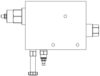
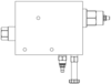
Solenoid-controlled priority bypass flow divider assembly
Capacity:
Loading...
Model
XPHSLGNNM
 | |||
 |  |  |  |
 |
Function
A - Normally Open 1 to 2

N - Normally Open 2 to 3

Technical specifications
Modifiers
Ports
- M, M/SPorts CF, EF, and P: SAE 16; Port T: SAE 4;
- X, X/SPorts CF, EF, and P: 1" BSPP; Port T: 1/4" BSPP;
This assembly provides an efficient way to supply auxiliary hydraulic power to various systems. The assembly divides the inlet flow of Port P into a priority flow to port CF with excess flow to port EF, with ON/OFF control provided by the FLeX Series solenoid-operated directional valve. With the FLeX valve energized, the priority flow to CF is controlled via the adjustable needle valve. Maximum pressure to port CF can be independently adjusted with the relief. When not energized, all the flow will be diverted from port CF at 100 psi (7 bar) to port EF. The system will reach maximum pressure at maximum flow.
- Sun Priority Flow Control assemblies utilize bypass/restrictive modulating elements, when combined with an adjustable needle valve, create a bypass/restrictive flow control. Inlet flow port P is directed to the priority or control flow at port 2 to the needle valve. The after-orifice (needle valve) signal is connected to port 1. Once the priority requirements are met, excess flow is bypassed to the EF.
- The bypass/restrictive modulating element (LH*A) requires 100-psi (7-bar) differential pressure across the throttle valve before modulating to allow flow to EF port.
- <strong><i>Note:<i></strong> Fully opening the needle valve may not generate the 100-psi (7-bar) differential required to shift the bypass/restrictive modulating element allowing flow to the EF port. The needle valve will need to be adjusted to ensure bypass flow to the EF port.
- Body TypeLine mount
- Capacity60 gpm
- Mounting Hole Diameter.36 in.
- Mounting Hole DepthThrough
- Mounting Hole Quantity3
Model CAD Files
Click the link of the file format you want to download.


Why doesn't Sun anodize their aluminum bodies?
How big is a drop of hydraulic oil?
Direct acting or pilot operated - what do I use?
- Important: Carefully consider the maximum system pressure. The pressure rating of the manifold is dependent on the manifold material, with the port type/size a secondary consideration. Manifolds constructed of aluminum are not rated for pressures higher than 3000 psi (210 bar), regardless of the port type/size specified.
- For detailed information regarding the cartridges contained in this assembly, click on the models codes shown in the Included Components tab.
Highlights
Technical Tips


Technical Information
- PartDescriptionQuantity
- 280-039-031*Orifice1
- A330-006-002*SAE Plug1
- A330-006-006*SAE Plug1
- A330-006-010*SAE Plug1